Jump to:
Jump to:
The production of die-castings includes a number of steps, any of which can result in a defective casting if not properly executed. Since repairing bad castings can be expensive, it’s important to avoid defect occurrences if possible. We’ll look at some common to areas of die casting defects — including wall thickness and die surface porosity — their causes, and how to avoid them.
You Can’t Correct and Control Defects if You Can’t Measure and Report Them
Without a scrap reporting system in place, it’ll be difficult to manage the quality aspects of your production line. An effective reporting system makes information available to everybody involved in the production process on a daily basis. The daily scrap report should categorize scrap for easy tracking by:
- defect type
- part number
- die
- shift
- operator
- machine
The report for the previous day’s activities should be available first thing every morning. Your scrap reporting system should capture long-term trends, and, ideally, it should predict customer rejects based on the recent scrap activity. Pareto charts are effective ways of illustrating reject activity. The report should also capture the defects that aren’t identified until the parts have made their way downstream — and you’ll want to develop a system to track these defects to the shift and machinery that produced them. Everything should be included on the scrap report, including warm-up shots and scrap returned to the furnace at the point of machine.
Don’t Ignore the Importance of an Effective Rating System
The die casting manufacturing process is complex, so it’s imperative your reporting system be continuous and provide real-time feedback to help you control defects. Now that you’re armed with accurate, real-time information, how will you decide which of the defects require immediate attention? That’s where a good rating system comes in handy.
An effective rating system will help you understand if you’re successfully reducing defects or if the problem is worsening. Importantly, it will let you know if changes you’ve implemented to reduce defects are having the desired effect. The bottom line is you want to know when corrections are necessary, and you want to know this before the defect levels reach crisis proportions.
Surface quality and porosity are two major die-casting defects, and both require judgments to be made about their severity. Let’s use porosity as an example to see what a rating system might look like.
Let’s rank a porosity defect on a worst to best scale of one to five. You could conduct a simple study as follows:
- Taking six sets of five sequential casting samples, at intervals of roughly one-half to two hours.
- Then rating each casting and averaging the total to give you the average quality level. You can compare these results with the outcomes of similar studies to understand the state of your process.
There’s no doubt defect corrections have to start with an effective scrap reporting system. The age-old adage “you can’t improve it if you can’t measure it” definitely applies to your die-castings.
What Causes Die Casting Defects?
Surface-area defects are a major concern with die casting that can be caused by a number of factors related directly to the casting itself.
Wall Thickness
Different wall thicknesses deliver different results. For example, a thin wall will cause the alloy flow to freeze and facilitate faster cold flow, or deformation. Minimum wall thicknesses for aluminum and magnesium are typically about 1.5 to 2.5 millimeters, while the minimum wall thickness for zinc is about 1.0 millimeter.
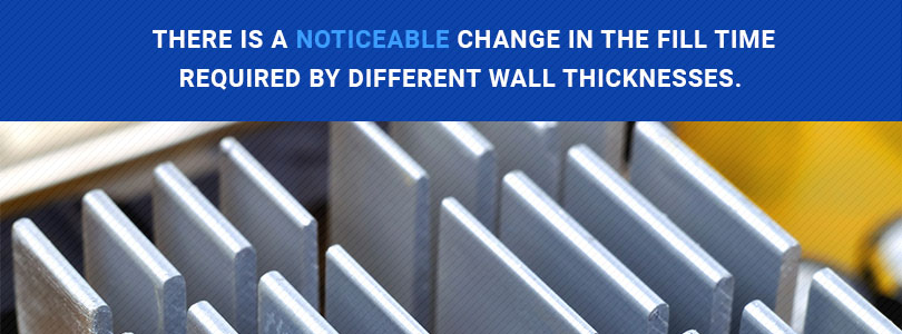
For example, there is a noticeable change in the fill time required by different wall thicknesses. A wall thickness of between 2.0 and 1.5 millimeters requires a 25 percent reduction in fill time, while a thickness of 3.5 to 3.0 millimeters requires a 12 percent reduction. So a small variation in fill time for a thin wall casting of 2.0 millimeters has a noticeable effect with no surface defects, while the same fill time for a thicker wall — let’s say 5.0 millimeters — has a less-noticeable effect.
Die temperature is much more critical in a thin wall casting because the reduced mass of the part won’t provide enough heat for the die. That’s not good because the very basis for a sound thin wall casting is very fast fill time in a hot die and high gate velocity.
Fill Time
The fill time begins when the alloy first arrives at the gate and ends after the cavity is filled with metal. Rough guidelines for maximum fill times that are applicable to most castings:
| Alloy | Thin Wall <2 millimeters | Average Wall >2 millimeters |
|---|---|---|
| Aluminum — approximately 2 kg | .09 seconds | .1 seconds |
| Zinc — approximately 1.4 kilograms | .03 seconds | .05 seconds |
| Magnesium — approximately 1 kilogram | .02 seconds | .03 seconds |
Predicting the fill time is achieved with the PQ2 calculation, which predicts changes in fill times and gate velocities because of changing any of the following:
- Gate area
- Plunger size
- Machine hydraulic pressure
- Plunger speed setting
It is really the only way to predict fill time. The only other way is the more expensive “guess” method, which is not recommended.
Metal Flow Pattern
The metal flow pattern is the key in gate design, which is a function of design rules espoused by the North American Die Casting Association:
- Employ the PQ2 calculation to size the gate and plunger — be sure to use the correct gate velocity, fill time and cavity pressure criteria
- Divide the casting into zones
- Proportion the gates so each zone is filled at the same time
- Flow across the casting
- Try to avoid mixing flows
Die Temperature
Low die temperature cools the fluid metal stream, affecting surface defects by increasing the amount of solidified metal in the stream. If the percent amount of solid metal is high enough, the stream becomes stiff and solid and doesn’t mix effectively, causing the flow to form cold-flow “wrinkles.” You can compensate for a cold die with a shorter fill time, which means increasing the plunger speed. The takeaway is you can exchange plunger speed for die temperature.
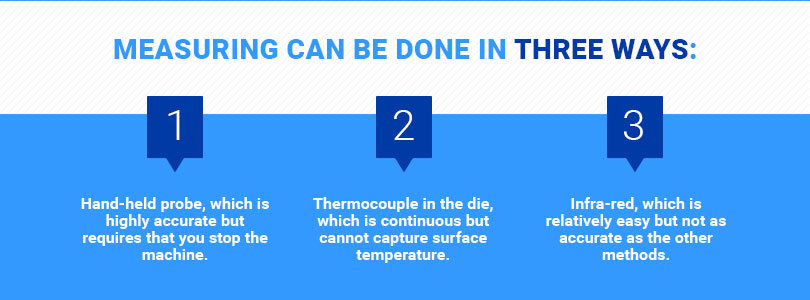
Because die temperature is so important to minimizing surface defects, measuring it should be a regular part of the production process. In general, measuring can be done three ways:
- Hand-held probe, which is highly accurate but requires that you stop the machine
- Thermocouple in the die, which is continuous but cannot capture surface temperature
- Infra-red, which is relatively easy but not as accurate as the other methods
Here are approximate temperature ranges that will ensure good surface finishes:
| Metal | Good Finish | Average Finish |
|---|---|---|
| Aluminum | 250 - 315° C | 190 - 315° C |
| Zinc | 230 - 290° C | 190 - 290° C |
Cycle time is another key aspect of die temperature. The temperature is directly influenced by the number of pounds of metal fed through the die in the previous one or two hours. Maintaining a consistent cycle time is one of the most important things you can do to control die casting defects.
Laminations
Laminations are usually the result of metal flow conditions in which one flow sits on the top of another and they are both too cold to mix. The way the metal flows inside the casting, which may be influenced by the casting’s geometry, may cause this layering effect. If geometry were the problem, changing the flow pattern via gate modifications would be very difficult. Instead, consider these:
- Decrease the fill time
- Increase the die temperature
- Increase the metal temperature
Of these options, a change to the fill time is generally most effective. Laminations often occur when metal is splashed into the cavity while the plunger operates at minimal speed. The remedy is to increase the length of fast shot, moving the switch closer to the pour hole. Die flexing can also cause laminations, caused by flexing of the die, which can result in an additional layer of metal outside the original casting skin. The fix here added support to the die.
Issues with Oxide Skins
Oxide skins are also known to cause lamination. These skins are generated in the holding furnace, or they may be created during injection in the cold chamber. They’ll be located randomly and are typically very small — 2 millimeters — and can be mistaken for porosity when dislodged by machining or sanding. There are a number of corrective actions you can take if oxide skins are the problem:
- Proper skimming of the holding pot
- Minimizing the amount of time in the cold chamber
- Filtering
- Proper fluxing and degassing
Another cause of laminations: Flash in the casting. This occurs when the die is dirty and the flash residue left on the die falls into the cavity as the die closes. The flash will not be remelted by the incoming metal, and therefore will not mix with the rest of the casting. The molten metal may in fact be barely able to adhere to the flash, making the flash a weak spot and causing cracks in the casting and layers on or near the surface. Corrective actions to reduce flash include:
- Keep the die clean in between shots
- Maintain a regular die maintenance and repair schedule
- Implement good process designs to ensure proper metal selection
- Maintain proper intensifier settings
- Keep dies expansion even by engineering the die cooling
Porosity
Porosity is another major die casting problem, and there are two types:
- Shrinkage
- Gas
It’s important to determine the type of porosity before trying to fix it, because each requires a completely different approach, although they can look similar. To be sure you’ve accurately identified the type of porosity defect you’re dealing with, use five- to ten-power magnification.
We’ll focus on gas porosity, since it’s the bigger problem of the two.
Gas porosity is one of the most significant problems in die casting. High gas content eliminates heat-treating or welding steps and makes the strength of the casting unpredictable. Here are three major sources of gas porosity in die-castings:
- Trapped air
- Steam
- Gas from lubricant
Trapped Air
Turbulence may allow air bubbles to be trapped in the metal. The problem is that the bubbles remain trapped when the casting solidifies. Air can be trapped as follows:
- Shot sleeve
- Runners
If Air Becomes Trapped in the Shot Sleeve
Your first step should be to maintain the same pour rate and shot delay time. This is particularly important at times when the fill is below 50%, because at this percentage of fill a wave may be generated by the act of pouring. The
air wave may travel from the parting line to the shot to and back again. When the plunger tip starts to move, its speed and acceleration are pre-designed to prevent trapped air bubbles.
If the wave collides as it moves forward, extra splashing is generated, capturing some bubbles. However, if the tip starts to move forward after the wave has been redirected away, the tip follows the wave, providing your best opportunity to minimize trapped air. A timer that establishes the time delay between end of pour and commencement of the shot will influence when the tip starts to move forward in relationship to the wave.
The acceleration of the plunger to slow shot speed is another contributor to trapped air. The plunger’s rate of acceleration should be slow enough to keep the metal from tumbling over, or surfing, but fast enough to stop air from getting trapped between the wave that’s generated and those waves that are redirected away from the die.
The acceleration rate will vary based on the percent of fill and length of the sleeve. The typical range is between two and less than three inches per second, per inch of travel.

How to Reduce Air in the Shot Sleeve
If you need to reduce air trapped in the shot sleeve, adjust the following settings until you have the problem resolved. Each of these settings alone may not seem significant, but there are interactions between them, and we recommend that you be as consistent as possible once you find a combination of settings that works for you:
- Fast shot starting point
- Rate of pour
- Shot delay time before the shot
- Speed of pour hole
- Pour hole to slow shot changeover speed
- Acceleration of slow shot
- Speed of slow shot
If Air Becomes Trapped in the Runners
Sharp corners and area changes in runner systems’ metal flow path can cause air to be trapped. Generally, the runner has smooth, rounded corners and is always decreasing in area from plunger to gate. As the metal starts entering the cavity, it will typically flow at high-velocity, extremely turbulent flow conditions, trapping some of the air as gas porosity.
A remedy is to design the flow pattern so that the metal tends to direct the air through the cavity and to the vents. A lot of the air in the shot sleeve and the cavity can be directed out of the vents or vacuum system, but the vents need to be sized correctly, extend to the edge of the die, and be cleaned routinely to avoid flash and lubricant buildup.
Working With a Pro to Avoid Die Casting Defects
We’ve just scratched the surface of die defects, their causes and the impact on castings. There’s a lot more to know, and it pays to work with a company that’s an expert in all aspects of die casting production and trouble shooting. Premier Engineered Products has been helping customers produce quality products for more than 50 years, so contact us to see how we can help you.