


Jump to:
- Parting Lines for Die Cast Components and Products
- Flash Formation and Location
- Proper Draft for Die Casting Parts
- Radii & Fillet
- Wall Thicknesses
- Ribs, External Corners & Metal Savers
- Die Casting Lettering, Symbols & Ornamentations
- Incorporating Bosses Into Die Cast Design
- Cast Surface Finish on Die Cast Parts
- CAD Feature Order
- Focus on These Principles for Successful Die Casting Design
Nearly every part of a product, or the entire product, has its genesis in the die casting process. Die casting describes a manufacturing process that allows manufacturers to create sharply defined smooth- or textured-surface metal parts. Utilizing a cold- or hot-chamber manufacturing technique that relies on high-pressure, the process forces and injects molten metal into a reusable steel die at a speed of 60-100 miles per hour. A number of clamps holds the mold in place during the injection, cooling and solidification stage.
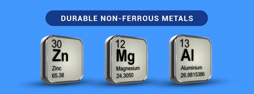
Similar to the injection molding process, which uses another class of materials, die casting produces parts from a durable range of non-ferrous metals, such as zinc, magnesium, aluminum and an array of composite materials. The type of metal chosen to fabricate the part determines whether the manufacturers will use the hot chamber or cold chamber method to inject the metal into the die.
Many manufacturers prefer die casting over other manufacturing processes because of the ability to create such an array of parts and products at high-speed and with precision. The current uses for die castings include machinery, vehicles, appliances, toys, sporting goods, office equipment heat sinks, enclosures and many other applications.
In addition, die casting enables the production of components with fine details like lettering, textured surfaces and other features without the need for additional processing. The ability to maintain close tolerances, which often eliminates all machining, makes die casting suitable for lower-volume products as well.
In recent years, innovations in manufacturing technology and material science have eliminated many of the old design assumptions and process challenges. These advances have resulted in new specifications for essential design elements, including dimensional control, draft and flatness.
For designers involved in die casting, here are some tips and hints on how to design your part or product efficiently and economically.
Parting Lines for Die Cast Components and Products
One of the most important elements of die casting design will be to decide on some type of parting line that will split the part and produce a contact surface between two or more components. Where the designer places this line depends on the geometrical shapes and the tolerances of the different surfaces. The designer has two choices — either a straight parting line or a broken parting line. You should try to design parts with a straight parting line because it is the least expensive option as far as tooling costs. When making a decision on the parting line, the designer should consider the following factors:
- Customer’s specifications — Usually, the part or product specification of the customer will make it challenging to place the parting line. The customer’s tolerance requirements also become an issue because parting line surfaces tend to have a lower quality compared to other surfaces.
- Die costs — A straight parting line can lower the cost of tooling. However, in some cases it will be more economical to design a broken parting line. This is due to adding features in the part that would require side die pulls, which are usually more expensive than stepping the parting line.
- Machining — Many parts require post -production machining. Areas that have critical tolerance or finishing requirement should be located to one side of the die In addition, the area near the parting line should not have essential cosmetic requirement because the gates and vents that will be positioned along this line will be visible. Furthermore, this area will need additional processing to minimize or remove material from the casting.
- Metal flow — The importance of the filling process depends on the proper placement of the gate inlet. The inlet, which must be located in the parting line, determines if the casting fills properly with the molten metal. Under high-pressure die casting, the injection or filling mechanism can press the metal into the casting to prevent the part from shrinking during solidification.
- Cores — The positions of cores (cores form holes in the part) will determine the placement of the parting line. The designer must consider the location of the core, as well as the size of the diameter and length of each core for each hole needed in the casting.
- Knockout Pins (also called ejector pins) — The parting line location decides the degree of force required to knock out the part when pressure die-casting. You should try to avoid undercuts when possible, but especially parallel to the parting line. These features may require additional die components or machining.
In the die casting design process, metal flow is one of the most important considerations. If the mold does not fill correctly, it can result in defects such as visible surface flowlines and air pockets that create internal porosity in the part. You will also need to consider the ejector pins that will eject the casting part from the die. You must design the pins in a manner that leaves a minimum number of residual pin marks on the surface of the casting. In addition, the ejector pins keep the part from bending. Ejector pin marks result in depressed or raised impressions of about 015” (.381 mm). The diameter of the ejector pin marks will vary depending on the size of the casting. For optimal manufacturability, use raised ejector pin marks.
Flash Formation and Location
At the parting line of the two die halves, an extension of metal can form on the casting or where separate die parts cast a feature. In addition, a seam of metal can result from regular operation of the ejector pins. You can account for this flash in the design phase and determine the amount of metal you must remove as well as the method of removal. Dealing with issues early during the design phase may produce cost savings for the overall manufacturing process.
Proper Draft for Die Casting Parts
The designer must incorporate drafts in the casting. The draft refers to the taper or slope assigned to cores and other parts of the die cavity. This element prevents the casting from getting trapped in the mold or tool during the ejection of the casting, making it much easier to open the die and easily eject the casting from the die casting die. Always try to introduce drafts in the process as early as possible. The drafts start from the parting line. The placement of the draft — on an inside wall, outside wall and/or hole — will have different calculations. The variations in shrinkage will determine the correct calculation (amount of draft).
Generally, in the formula, the figure is always a constant. It depends on the alloy used and the depth of the surface. However, any die cast surface that is parallel with the opening direction of the die should be tapered for proper ejection of the part from the die. In this case, the draft requirement results in an angle and is not constant.
Outside wall placement requires the least amount of drafts because the casting tends to shrink away from the die steel forming outside the surfaces. In contrast, untapped holes require the most draft. As the casting shrinks during solidification, it exerts great force around the die steel, which forms the interior surface of the hole. The inside wall also undergoes casting shrinkage onto the die steel that creates the surfaces of the inside walls.
A die that is easy to open and get the part ejected will result in a part that is more precise for straightness/flatness and one that has a higher surface quality.
Radii & Fillet
 The use of both fillet and radii can increase structural integrity. To promote metal flow, use a liberal radii and transition. For intersecting surfaces that meet at a sharp corner or edge, fillets can prevent high stress concentrations at the juncture, in both the die casting die and the parts. Fillets reduce the concentration of heat in the die and the part. The proper use of fillets will reduce the die maintenance costs and increase the life of the tool.
For a fillet projected in a location that is perpendicular to the parting line, you must add draft. The amount of draft depends on the draft of the intersecting surface. To maintain continuity for the edges and smoothness for the components, create constant-radius fillets. Shallow castings tend to have smaller fillets. Deep pockets and other inside corners require larger fillets.
Wall Thicknesses
Generally, die castings consist of thin-wall structures that do not have any hard and fast rules for minimum and maximum wall thicknesses. It is important to design uniform walls throughout the part and where variations occur. This will ensure a smooth metal flow during filling and minimize distortion caused from cooling and shrinkage. A good mold filling will produce parts with excellent properties and few defects. The key is to design the casting so the entire mold fills before solidification begins. Failure to fill the whole mold first could lead to cold shuts (poor surface finish) in the casting. You can reduce the risk of cold shuts without any sharp or unnecessary corners, which impede the melts flow in the mold, by using radii.
Innovations in die casting technology make it possible to produce parts with minimum and maximum thicknesses that were unattainable a few years ago. Utilize this capability only when you find it necessary to enhance performance or to achieve economic benefits. Otherwise, stick with uniform wall thicknesses. You can make the metal flow better through the mold with thicker walls and ribs. When the main wall has protruding features, make sure they do not add significantly to the thickness of the wall. Excessive bulk can delay cooling.
When viewing the part from the die opening direction, make sure the features that project from the side wall do not lie behind one another so you can avoid die casting depressions.
Although design casting allows for the production of intricately detailed components, the designer should avoid the use of interior undercuts when designing the parts because the moving interior core mechanics are difficult to operate. You can produce this feature by machining, which increases part cost but reduces the tool cost by avoiding core pulls in the die.
Ribs, External Corners & Metal Savers
When you design a part, you must add ribs on thin walls. Ribs can increase the stiffness and add strength to fabricate a more solid part. Often, the addition of ribs can do more to strengthen a component than solid material because of the porosity, and ribs result in a lighter part. Improper rib design can result in the concentration of working stresses or the creation of unnecessary stresses at the edges of the ribs. You must place the ribs in the proper locations for the ejector pins to be placed on the ribs for ejection strength.
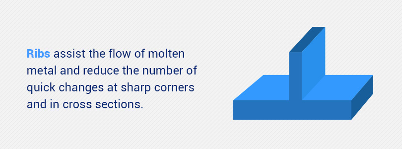
Ribs should assist the flow of molten metal. Whenever possible, include radii and fillets with ribs to reduce the number of quick changes at sharp corners and in cross sections. It also allows for improved ejection of the casting. Design into the part an odd number of ribs. This technique eliminates the buildup of stress across to an adjacent rib and reduces the formation of thick intersections.
External Corners — Occasionally the die casting die may have sharply squared external corners at certain locations. At parting line locations and die block intersections, the designer must have this type of corner. On other corners, the design should incorporate radii to avoid premature die failure. It also reduces the chances of damaging the edge of the part during handling and assembly, and it enhances safety for the personnel who handle the material.
Metal Savers — Ribs have empty spaces between them called “metal savers.” Metal savers do not serve a functional purpose. However, when you design your parts, keep in mind that positioning ribs too close together can cause weak metal savers. When you design your parts, evaluate the design for the following design weaknesses.
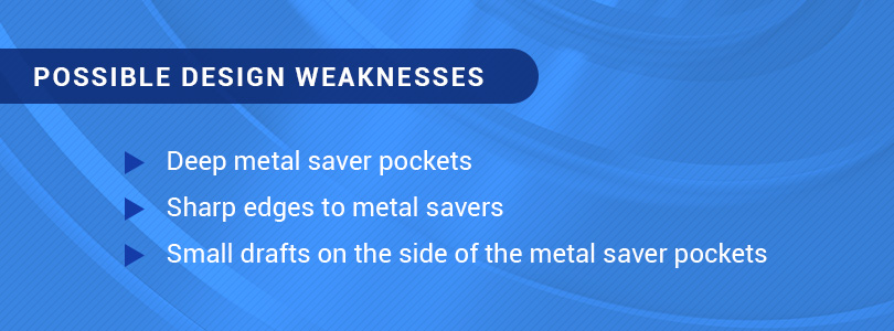
When designing your part, review the specifications as it relates to metal savers to avoid compromising the integrity of the part.
Holes & Windows — Holes and windows may be among the most important considerations for design geometry. This element affects the molten metal flow through the component, and the configurations play a critical role in the manufacturability and the final quality of the component. The perimeters of holes and windows tend to latch onto the die steel during the cooling period, which can have an effect on the ejection of the part from the die. Remember, when calculating the draft, the holes and windows require more draft, compared to inside and outside wall features. For recommended drafts. refer to the NADCA Product Standard Publication #402. Draft charts are included in Chapter 4, Standard S-4A-7-15.
Die Casting Lettering, Symbols & Ornamentations
Many casted parts require the designer to add lettering, logos, trademarks and other identification to the casting. Other castings have date marks to identify the manufacturing date to differentiate one batch from another.
Manufacturers use two methods to create these characteristics. The first technique, which is the most common and cost effective, uses raised letters. In addition, because this method embeds the lettering into the cavity, they last longer. The second technique depresses the letterings into the component by forming protruding characters on the die. This technique is more expensive to make in the die and it makes the characters susceptible to wear and requires more maintenance.
Incorporating Bosses Into Die Cast Design
Many parts require bosses to function as mounting points and standoffs. When adding this feature, the designer must take great care to maintain consistent wall thickness. This will require the addition of a hole in the middle of the boss. In addition, the inner and outer surface requires a draft. It is difficult for molten metal to flow up a tall narrow boss feature to fill it to the maximum level. Because of that, die casting designers usually add a generous amount of fillets and ribs (gussets) to assist the flow of the molten metal into these areas and to facilitate the ejection of the part from the die.
Cast Surface Finish on Die Cast Parts
The finish on the tooling will determine the finished surface of a die cast component. A highly-polished finish on the die will produce good surface casting parts. The surface roughness of most tooling makes it easy to produce a matte finish. Some decorative cast components and other casting parts and products require the application of an external surface finish.
So designers and manufacturers can plan for as-cast surface finishes from the outset of the die design, the NADCA divides finishes into five classes and offers the following guidelines:
- Class 1: Utility Grade — This class does not have any cosmetic requirement for as-cast finishes and allows for cold shut, rubs, porosity, lubricant build-up and other imperfections. The end-use finish can be as-cast, or the customer can choose a protective coating such as anodize (non-decorative) or chromate (yellow, clear).
- Class 2: Functional Grade — Allows surface imperfections that can be removed by spot polishing or covered by heavy paint. For the final finish, the customer may select decorative coating, such as lacquers, enamels, plating (Al), chemical finish or polished finish.
- Class 3: Commercial Grade — Permits the removal of surface imperfections by methods agreed to by the customer. For the final finish, the design can call for structural parts in high-stress areas. Other options are Plating (Zn), electrostatic painting and transparent paints.
- Class 4: Consumer Grade — This grade has non-objectionable surface imperfections. In the case of rejection because of surface waviness (flatness), as noted by the reflection of light, the customer can determine a course of action in agreement with the die caster. For end use, the designer can use decorative parts.
- Class 5: Superior Grade — The finish that applies to limited areas on the part has a maximum value expressed in micro-inches on the print. The end use consists of O-Ring Seats or Gasket areas.
As-cast surface categories do not apply to machined surfaces. The designer must identify finished machined surfaces separately on the design drawing. The customer and the die caster must agree to the final selection.
CAD Feature Order
To facilitate the development of a die casting design model and to reduce the possibility for feature tree errors, NADCA recommends the use of the following CAD Feature Order:
- Base geometry features: Put the features that comprise the base geometry of the model at the top of the feature tree, including bosses, extrusions, revolves, cuts, shells, lofts and sweeps.
- Cast cored holes: Holes that you will cast during the manufacturing process, and which you may or may not tap or machine later.
- Parting lines: Placing the parting lines next in the feature order including any parting line that appears in a component after applying the draft.
- Draft: This feature goes next.
- Fillets: Add fillets to all geometries, with the exception of some parting lines.
- Machining: Lastly, add all machine features at the end of the feature order — suppressed and un-suppressed.
Putting machining features last allow effortless creation of as-cast and machined model configurations. This is a good way to identify as-cast features and features that require machining. Sometimes, very large fillets, draft or highly tapered components may be included in core geometry features. Position these design elements at the top of the feature order tree.
Why Die Casting Is Beneficial for Designers
Die casting allows designers to create basic parts with add-ons and simultaneously cut back on the assembly and machining costs. It’s also an excellent solution for many processes, from producing parts to decorative trim and finished products.
Die casting offers several notable benefits for production designers, with a few examples including:
- Production rate: Die casting moves at a high production rate with little to no machining necessary.
- Complex shapes: The die casting process can produce mass products with advanced shapes and designs with close tolerance.
- Quality: The die casting process produces parts that have durability and stability with the feel and appearance of five-star quality.
- Surface types: A die cast can simulate surface textures with a selection of various materials. The surface of a die-cast part is also exceptionally smooth compared to other casting methods, including sand and permanent mold.
- Corrosion resistance: Most die-cast alloys like zinc or aluminum have moderate to high corrosion resistance properties.
- Durability: Since die casting creates a single part, these products are stronger than parts produced by welding or fastening.
Focus on These Principles for Successful Die Casting Design
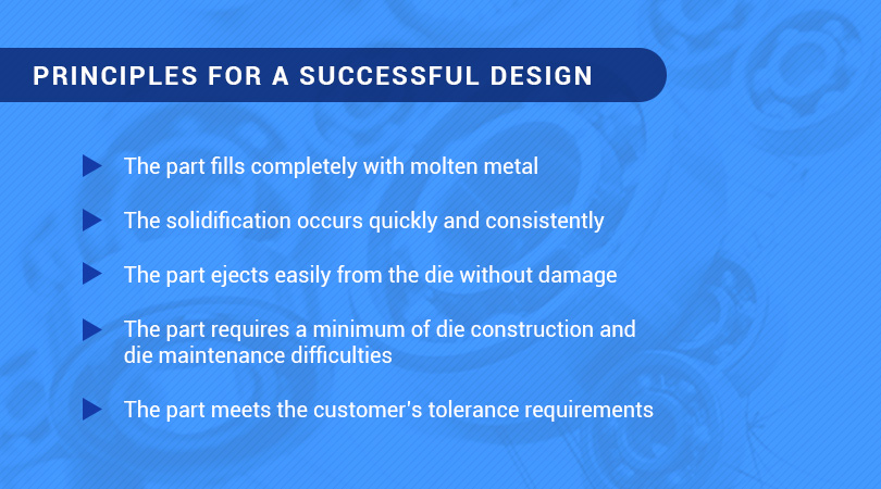
In summary, along with the functional requirement, the designer must incorporate numerous manufacturability-related-factors into the design of a part or product to produce successful castings economically. To achieve this overall design goal, keep the following objectives in mind during the design process:
To learn more about the die casting services offered by Premier Engineered Products, contact us online today.
Thanks for your post. Die casting looks like it can be used for just about anything. Its good to know that die casting can reflect the exact details that you want it to. The ability to not have to do any or hardly any processing after that casting process is a major time saver for companies.